Landing and Taxi Lamp Current Sensing
For some reason, in both the TB and the TBM aircraft, Socata sense the current drawn by the landing and taxi lamps, with current sensing relays, and use those relays to switch the annunciators in the pilot instrument panel. One can understand that for the pitot heater whose operation cannot be otherwise verified (which they do in the same way) but the lights are easily visible to the pilot...
The problem with retrofitted LED lamps is that they draw a lot less current than the old lamps (about 1.5A versus about 4A) and on all 24V aircraft the reduced current fails to energise the current sensing relays. In some cases it works OK on 12V aircraft where the LED lamps draw 2x more current.
The current sensing relay (example schematic) is clearly not safety-critical, but it's obviously undesirable (and arguably illegal) to have defunct indicator lights in the cockpit.
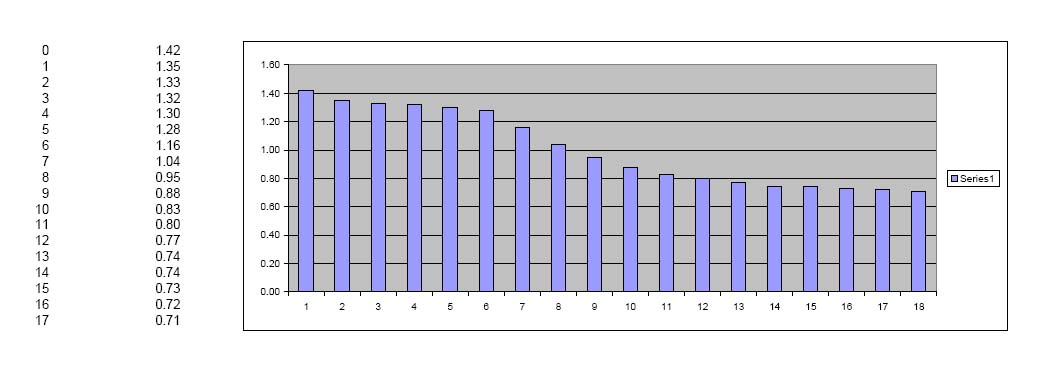
A further issue - with some of the LED lamps at least - is that their current reduces substantially as they warm up, especially if they warm up above a certain temperature. The AeroLED lamps which I installed drop as follows, in a bench test in which the lamp temperature eventually reached +70C
The X axis in the above chart is minutes. I checked the brightness with a light meter and it really does drop off in line with the current as shown above! This means any comparison of lamp brightness, from the data sheets, is probably meaningless.
AeroLED's comment on the above data is that it is as expected, but I don't think many people realise just how soon the light output starts to drop off. Nevertheless the light output is always way above the old lamp!
There is no obvious forced air ventilation in the TB wing lamp area so clearly one needs to get the relay turn-on current down to about 0.5A, to be sure it will turn on even when the lamp is already warm.
I have unsuccessfully tried to find out from Socata the design parameters of this relay but in 2013 managed to obtain a PCB containing the three relays, from a crashed mid-1980s TB10
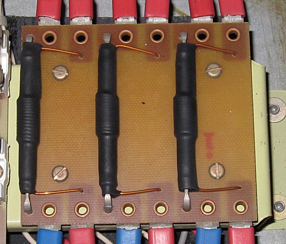
Each relay is formed in a rather home-made fashion by wrapping 14 turns of enamelled copper wire around a glass reed switch. The lamp current flows through this wire. I have measured the turn-on current of all three of the above relays at 2.3-2.4A (and the turnoff current at about 1.5A) which explains why they don't work with LED lamps. An obvious modification would be to increase the number of turns. The glass reed relays are extremely fragile, however, and if you break one then you need to find one with the same sensitivity, which may not be easy since they are unmarked. It would be better to find new reed switches of the correct size, rewind them to switch at 0.5A (which should cover all the decent LED lamps currently on the market, including the condition where the lamp has reduced its current due to heating), bench test them, and put them in.
On the above PCB, all three relays switch at the same current. The first two (from the left) do the two lights and the third does the pitot heater (which draws about 5A at 24V).
The reed switches are 50mm long. Looking for similar size switches digs out a DRA283 (RS page local copy data sheet) which is specified at 5A and at 60-120 ampere-turns. The RS one is a narrower spec of 60-80 AT which at 14 turns would switch at 4.3A-5.7A. Therefore, obviously, the ones Socata use are a lot more sensitive but that also means they are rated at a much lower switching current! That's not a good idea given they are switching incandescent lamps which have a high inrush current and will eventually damage the reed switch contacts.
For this application the DRA283-60-80 would need to be wound with about 130 turns, to guarantee switching below 0.6A which is the current to which the 36LX drops down to when warm. With a wire diameter of about 1mm, this is possible if wound onto a bobbin which is almost the full lenght of the reed switch, while keeping the diameter of the bobbin down such that the whole thing fits under the plastic cover of the fusebox where the PCB is located. The maximum height above the PCB is about 13.5mm.
With 1mm wire, the resistance of 120 turns is about 0.1 ohm so if an old 4A lamp was refitted by accident the power dissipation would be 1.6 watts, which is OK. One could use a thinner wire but then an old type of lamp could not be safely refitted, which would be a highly undesirable situation.
There is no need to modify the pitot relay.
It is VITAL to protect the glass reed switch when bending its leads, by holding the lead with long nose pliers which are placed on the "switch" side of the bend, so that no stress is placed on the glass.
Enquiries reveal that Socata went through three different designs of the above PCB, as the TB series progressed, but all seem to have the same size and style. The above picture, showing the bare reed switches, is the earliest design. Later they used encapsulated reed relays, with much smaller reed switches inside, with series resistors (15 ohms) to prevent the inrush current of the lamps from damaging the reed switches. That design went through two versions whose PCBs appear very similar and one of them is below:
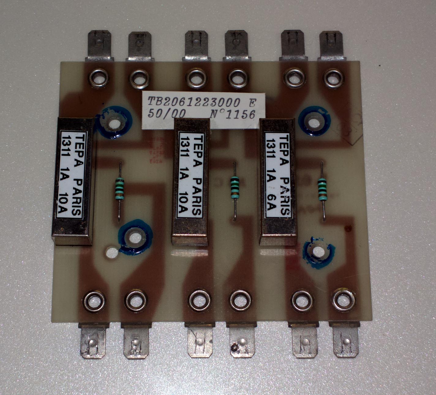
The turnon current of the above relays was measured at 2.2A 2.2A 1.6A (left to right). It's interesting why Socata dropped the pitot heat sensing threshold from 2.3A to 1.6A, given that the 28V pitot heater draws about 5A.
The two PCB styles are interchangeable in any TB aircraft, except for the later type having an extra mounting hole.
There is however a subtle difference between the two PCBs! The current sensing terminals, and the relay contact terminals, are swapped over! I have no idea why Socata did that, as the later PCB could have easily been laid out to match the original one.
An obvious way to modify the later type of PCB would be to source more sensitive versions of the TEPA relays, for the first two positions only, but the company - founded in 1977 - went bust in 2009. The above PCB was made in year 2000.
Another way to modify the later style PCB is to simply construct reed relays using the reed switches described higher up above, and secure them to the PCB using some suitable method.
It may seem obvious that in the 21st century one should use solid state sensing and use MOSFET switching, but that will need careful design to deal with scenarios where either or both of the lamp wires or the indicator lamp wires are swapped.
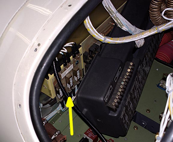
This photo shows the location of the original PCB in a TB20GT:
Modification legality
I am not aware of any precedent in this area.
For an N-reg, the starting point is FAR 43 Appendix A. See also here for some notes on Certification. It is down to an interpretation of the words "basic change to...the electrical system". I don't think rewinding the relays is a "basic change" but, as with any modification which is regarded as Minor and therefore not done under an STC or an FAA-approved Field Approval, one can never be 100% sure...
For an EASA-reg, I have no idea but it probably would be a Major modification which would require throwing some money at a Part 21 design company.
This page last edited 15th October 2013