
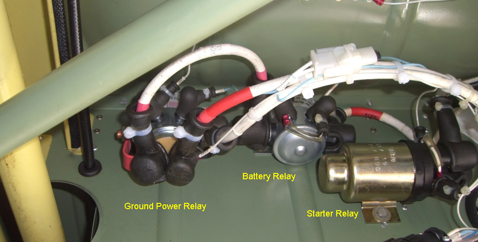
TB20/21 Ground Power Relay
On the 28V TB20GT, this relay disconnects the battery from the aircraft whenever external power is connected
This pic shows its location
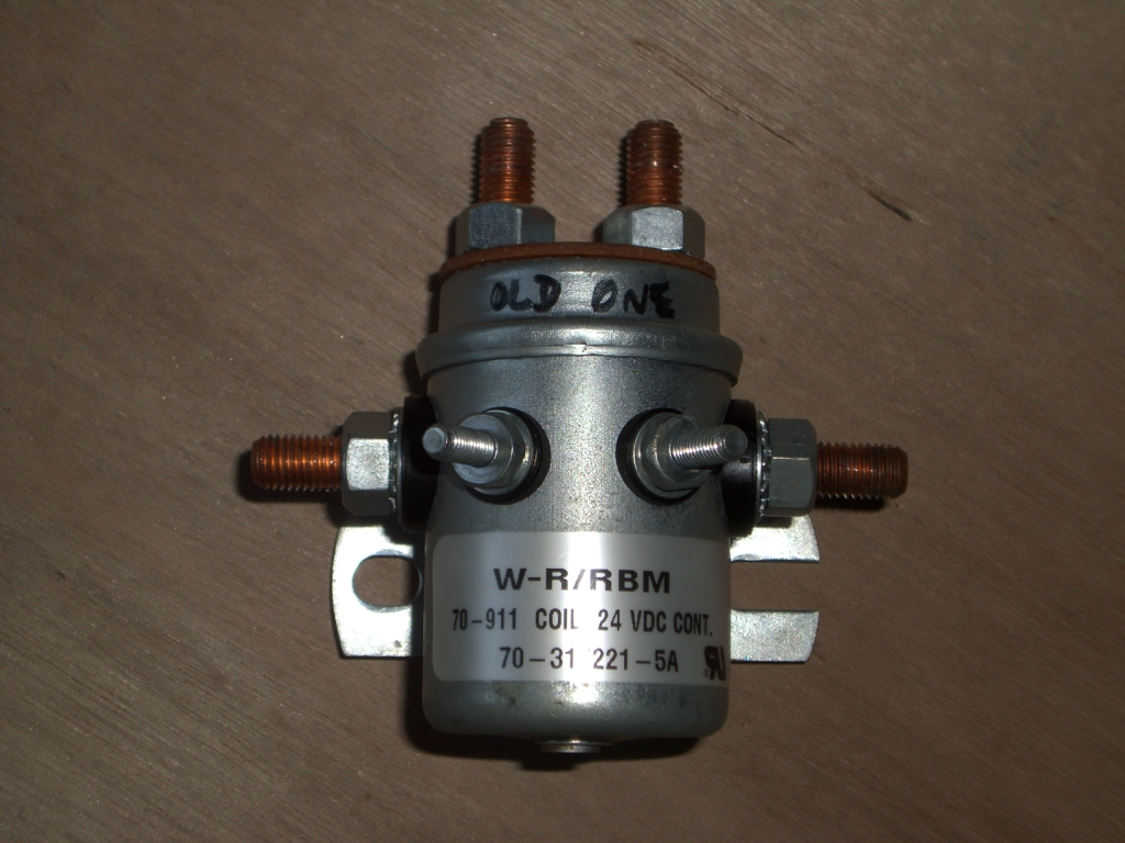
The relay specified by Socata is a Stancor 70-911 (data sheet local copy) whose N/C contact is rated at just 30A. This was clearly a design oversight since 30A is nowhere near enough for the current drawn by any starter motor, especially the higher-performance types e.g. Skytec which are routinely installed on both US- and EASA-registered aircraft, by Socata and by dealers everywhere. There is a rumour that the Socata relay has 50A contacts but I have not found any evidence for this, and anyway 50A is still nowhere near enough.
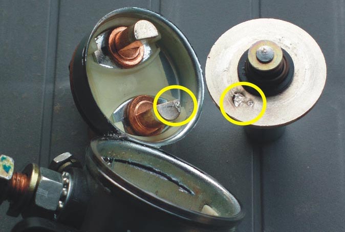
The result is that the N/C contact eventually welds together, preventing the use of external power. The relay solenoid does not have enough power to pull the welded contacts apart; this is obvious when one dismantles a welded-up relay:
This is not always a huge inconvenience but if you flatten the battery, you will have to remove it and put it on charge before you can fly again... Many pilots have a welded-up relay but are unaware of it because they never need external power.
One possible replacement from the same manufacturer is the Stancor 586-914 (for 24V aircraft) (data sheet local copy) whose N/C contact is rated at 100A, with an inrush current rating of 200A. On a US-reg aircraft, this relay could most likely be installed as a Minor Mod (referencing Part 43 Appendix A, this should not be a "basic change" to the electrical system) but it won't fit onto the existing relay's mounting holes so either an adaptor plate would be needed, or two new nutplates would need to be installed for the relay's mounting screws. Unfortunately, the 586-914 is not a TSOd part and does not come with any "approved data". The installation would therefore require a DER approval; even a Minor Mod cannot use parts without approved data.
The 586-914 relay (below, on the right) is quite a bit larger than the 70-911 and would almost certainly need longer cables to be made up. It is also heavier - 800g versus 400g for the original one
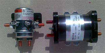
What is real eye-opener is an actual contact resistance measurement of the two relays above, on the N/C contact: 8.5mOhms versus 0.65mOhms - a difference of more than 10x in the power dissipated in this contact. At 100A starter current, the power dissipation in the original relay is 85W and this is concentrated in the tiny contact area!
There are other relay options which are much closer in physical format e.g. the Ametek SBD-5401 (local copy)
whose N/C contact is (in the silver plated contact option) rated at 150A. Unfortunately, a contact resistance measurement of this relay shows it to be no better than the Stancor 70-911... perhaps hardly suprising given its identical size and internal construction comprising of a conductive disk which is held against the N/C contacts by a spring.
I queried this with Ametek and their reply was: Part of the reason for the 150 amp rating is based on the use of a silver alloy contact material. The silver alloy has better conductivity properties than the copper. Also, the contact disk uses a special alloy to give it better anti-welding characteristics. We do not use contact resistance as a means of evaluating the contacts. We feel that the contact voltage drop gives us a better indication on of the condition of the contacts. Typically you will see an initial high voltage drop for new contacts due to films and breaking in of the contacts. As the unit further switches, you should see a reduction of the voltage drop.
However, further enquiries revealed that all these relays will eventually suffer an increase in contact resistance if they never switch current. The contacts, and the disk which bridges the contacts, suffer from corrosion, and the relay relies on switching a "real" current to keep the contacts clean. From Ametek: if it doesn't ever switch current, eventually you may have a situation where it may not carry the current. This is probably why the existing relay eventually fails! Neither of its contacts ever switches any current, and corrosion gradually increases the contact resistance until the contact power dissipation is sufficient to weld the N/C contacts to the moving disk. Nothwistanding this discovery, we still have the totally inadequate 30A current rating of the original Stancor relay, versus the 150A rating of the Ametek relay, and at face value there is no prize for guessing which one should be used!
The Way Forward?
Legally, nothing can be done, without following the full certification route. However, the above Ametek relay should comply with the Minor Alteration decision chain in Part 43 Appendix A because it is so similar to the Stancor one. I know these have been used by TB20 owners and they reportedly work perfectly.
The above 586-914 relay is a much better solution but one would need to be a lot more confident regarding the Appendix A process.
Practically, it appears obvious that - in the TB20GT case - the battery master relay and the starter relay are both strong enough to carry the starter current; only the ground power relay is a serious issue. The obvious thing would be to replace the ground power relay with the above Ametek one, and exercise it periodically with an external power pack, to give the internal disk a chance to rotate a bit.
The starter relay is made by Valeo but due to a total lack of co-operation or communication from Valeo it is impossible to find out any data on it. However, it looks like a stardard heavy duty commercial vehicle relay. If there was any doubt about it, one could easily replace it with a Stancor relay of a suitable known rating.
It may be tempting to re-wire the system to bypass the ground power relay, or even bypass the battery master relay. The former appears perfectly reasonable; indeed in some aircraft the external power unit will charge the battery. The latter is probably not advisable since a single relay failure (the starter relay) could cause the starter to become energised during flight, and this could cause an engine failure, or a fire which could not be extinguised by de-energising the battery master relay.
Starter Motor Issues
If using the Skytec starters, the 149-NL has often been installed because it combines excellent starting performance with a lower current draw than the older (original "lightweight starter") Skytec models.
However, in 2010 Skytec "discovered" that the TB20 can be 24V and not just 12V and following some reliability issues with the 149-NL they now recommend the EC version of it which is a 24V-only model which draws less current. The new 2010 applicability guide is here.
Obviously I think there is more to this than meets the eye. A motor which is "12/24V" should work on 24V...... There have also been numerous failures of these starter motors recently, some involving a failure whereby the end of the motor spun around through about 20 degrees, presumably ripping off internal connections in the process. It is possible that the long bolts which hold the motor together have been under-torqued on some units, or maybe the starter motor is genuinely not suited to 24V operation and is right on the margin. On my 149-NL starter, which has been in place for 3 years (since July 2007) the bolts show evidence of a very slight rotation; 1-2 degrees.
There may also have been numerous failures of starter relays in some aircraft types. This Cessna SB shows the Skytec installation but this accident report contains interesting information...
2/2016: the EC version runs at about half the speed! So that is how they solved the problem... more here It still works but obviously hot starts are more difficult.
This page last edited 25th February 2016